-

+86-13961903990

+86-13961903990
Industry News
 Home / News / Industry News / High Pressure Oilfield Valves in Wellhead and Pipeline Systems: Design and Application Guide
  2026.08.03
 Industry News
Content
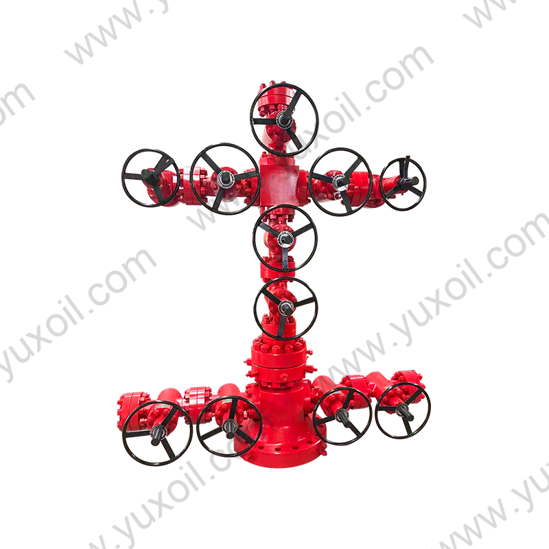
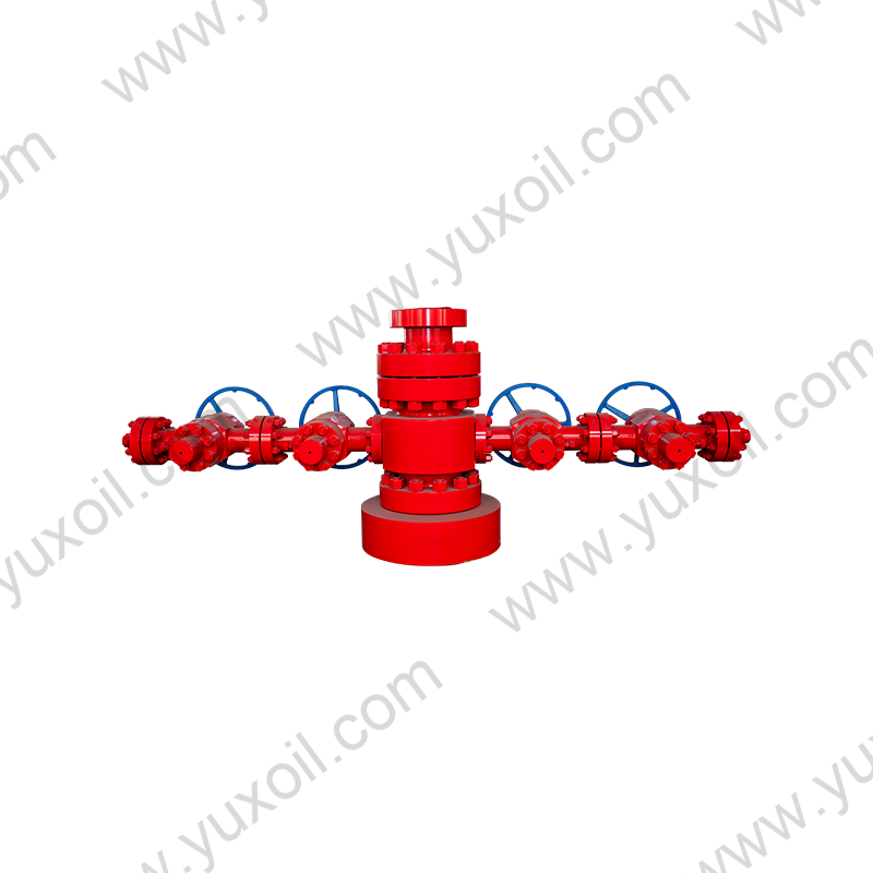
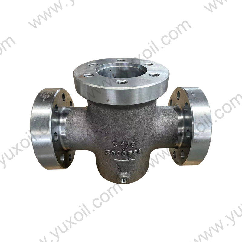
A high pressure oilfield valve is a valve engineered to safely control, isolate, or direct the flow of oil, gas, and process fluids at pressures typically ranging from 2,000 psi to 20,000 psi, used across wellhead assemblies, Christmas trees, frac trees, choke manifolds, and high-pressure pipeline segments. These valves are distinguished from standard industrial valves by heavier body wall thickness, forged (rather than cast) construction, stricter material traceability, and mandatory hydrostatic and gas testing to confirm they can contain pressure safely under both static and cyclic loading conditions.
Common Valve Types Used in High-Pressure Service
No single valve design fits every high-pressure application. The choice of valve type depends on whether the priority is full-bore access, bidirectional sealing, throttling capability, or rapid quarter-turn operation.
| Valve Type | Key Characteristic | Typical Application |
|---|---|---|
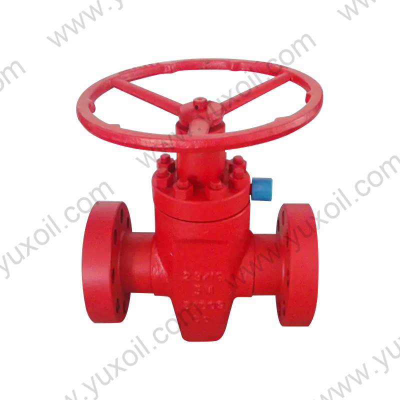
| Gate valve | Full-bore, through-conduit flow path | Wellhead master and wing valves |
| Ball valve | Quarter-turn, tight bidirectional shutoff | Pipeline isolation, subsea trees |
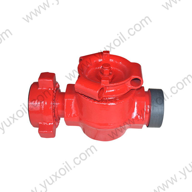
| Plug valve | Quarter-turn, resistant to abrasive flow | Manifolds, produced water systems |
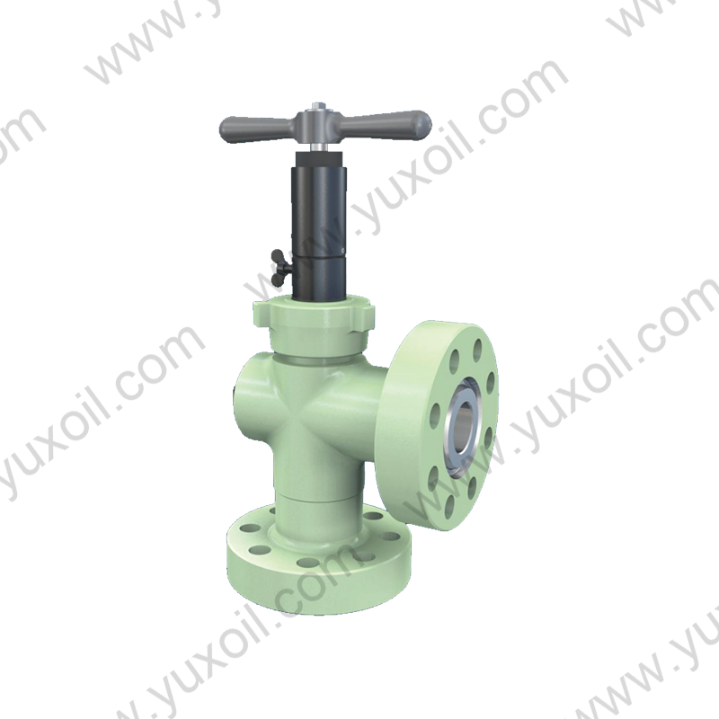
| Choke valve | Precise pressure and flow reduction | Wellhead choke manifolds, frac flowback |
| Needle valve | Fine throttling control on small bore lines | Instrumentation and sampling lines |
Gate valves remain the dominant choice for wellhead master and wing valve positions because their through-conduit design allows wireline tools to pass through the fully open bore without obstruction — a functional requirement that ball and plug valves generally cannot match in the same footprint.
Different standards apply depending on where the valve sits in the system — at the wellhead itself, on the Christmas tree, or downstream in the gathering or transmission pipeline.
A valve certified under API 6A carries a Product Specification Level (PSL) from 1 to 4, with PSL 3 and PSL 4 typically specified for high-pressure, high-temperature (HPHT) and critical sour service wells because they require extended design validation testing, full material certification, and more rigorous non-destructive examination than PSL 1 or PSL 2.
Pressure class selection is the single most important decision in specifying a high-pressure valve. Under-rating creates a direct safety hazard, while over-rating adds unnecessary weight and cost to the installation.
| Pressure Class (psi) | Rated Pressure (MPa) | Typical Application |
|---|---|---|
| 2,000 / 3,000 | 13.8 / 20.7 | Low-pressure onshore wellheads and flowlines |
| 5,000 | 34.5 | Standard production wellheads |
| 10,000 | 69.0 | High-pressure gas wells, frac trees |
| 15,000 | 103.5 | Deepwater and HPHT wells |
| 20,000 | 138.0 | Ultra-deepwater, extreme HPHT wells |
Every valve must also carry a temperature class, ranging from U (-75°F to 82°F) for arctic conditions to T (-18°F to 350°F) for high-temperature production. The temperature class should be matched to the actual flowing fluid temperature at the valve location, which can be significantly higher than surface ambient temperature in producing wells.
Material selection becomes critical once a valve is exposed to H2S, CO2, or elevated temperatures, since standard carbon steel can suffer sulfide stress cracking or lose mechanical strength under these conditions.
For example, a well producing at 15,000 psi with 300°F flowing temperature and detectable H2S would typically require a Material Class EE, PSL 3 or 4 gate valve with metal seats, whereas a low-pressure sweet gas wellhead at 3,000 psi could be adequately served by a standard Material Class BB, PSL 2 valve.
Every high-pressure oilfield valve must pass a defined sequence of production tests before certification, and higher PSL levels require additional design validation testing on a prototype before the design is approved for manufacture.
PSL 3 and PSL 4 valves additionally undergo extended cyclic testing, sometimes involving several thousand open-close cycles on a prototype, to simulate years of field operation before the design is approved for production — a step that significantly reduces the risk of premature seat or seal failure once the valve is installed downhole.
High-pressure valves are installed at every critical isolation and control point across the upstream flow path, from the wellhead through to the pipeline network.
Pipeline block valves in particular are often spaced at intervals of every 20 to 30 miles along a transmission line, allowing operators to isolate a ruptured or damaged section quickly and limit the volume of product released during an emergency shutdown.
Correct valve selection depends on matching well or pipeline conditions to the valve's rated pressure, temperature, material class, and PSL — not simply choosing the highest-rated valve available.
High-pressure valves operate under conditions that accelerate wear on seats, seals, and stem packing, making a structured maintenance program essential to avoid unplanned shutdowns or safety incidents.
Most operators schedule full recertification of critical wellhead valves every 3 to 5 years, with more frequent inspection intervals for frac tree valves subjected to repeated high-pressure cycling during multi-stage stimulation operations, where seat and seal wear accumulates far faster than in valves used for simple on/off isolation service.
 No. 161, Yanhe Middle Road, Yanhe Town, Jianhu County, Yancheng City, Jiangsu Province, China
 +86-13961903990
 +86-515-86598285
 +86-515-86590688
Copyright © Jianhu Yuxiang Machinery Manufacturing Co., Ltd. All Rights Reserved.
 Login Wholesale High Pressure Wellhead/Drilling Equipment Manufacturer

 English
 русский
 Español