-

+86-13961903990

+86-13961903990
Industry News
 Home / News / Industry News / Oilfield Plug Valves in Upstream Operations: Design, Standards, and Application Guide
  2026.07.27
 Industry News
Content
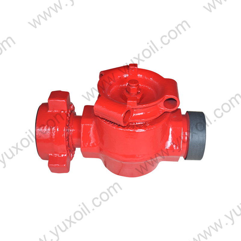
An oilfield plug valve is a quarter-turn isolation and flow control valve that uses a cylindrical or tapered plug with a bored passage to start, stop, or divert flow in upstream oil and gas systems. Plug valves are widely used across wellheads, manifolds, gathering systems, and produced-water handling because they offer tight shutoff, fast quarter-turn operation, and strong resistance to abrasive or multiphase fluids compared to many gate or ball valve designs.
How an Oilfield Plug Valve Works
A plug valve controls flow through a plug — a cylindrical or slightly tapered body with a through-bore — that rotates 90 degrees inside the valve body. When the bore aligns with the pipeline, flow passes through; when rotated a quarter turn, the solid portion of the plug blocks the flow path completely. This mechanism gives plug valves a simple, robust sealing method that does not rely on a separate seat ring wearing against a ball, which is one reason they are favored in abrasive or sand-laden upstream fluids.
Because the plug itself forms the sealing surface, plug valves generally offer lower operating torque and faster cycle times than comparable gate valves, making them a common choice where frequent switching between flow paths is required, such as in test manifolds and multi-well gathering systems.
Not all plug valves are built the same way. Selecting the right type depends on the fluid being handled, the pressure differential, and how frequently the valve will be cycled.
| Plug Valve Type | Sealing Method | Typical Application |
|---|---|---|
| Lubricated plug valve | Sealant injected between plug and body | High-pressure gathering lines, legacy systems |
| Non-lubricated (sleeve) plug valve | Elastomer or PTFE sleeve around plug | General upstream service, low-maintenance needs |
| Expanding plug valve | Plug mechanically expands into seat on closure | Bidirectional tight shutoff, custody transfer points |
| Eccentric plug valve | Plug lifts away from seat during rotation | Slurry, produced water, and solids-laden flow |
| Multi-port plug valve | Plug with multiple bore passages | Manifold flow diversion, test separator switching |
Eccentric plug valves deserve particular attention in upstream service because the plug's off-center rotation lifts it clear of the seat during opening and closing, drastically reducing seat wear when handling produced water with sand or scale — a common failure point for standard plug and ball valves in the same service.
Oilfield plug valves used in wellhead, pipeline, and surface production applications are typically designed and tested against a combination of API and ASME standards, depending on where in the system the valve is installed.
Valves built to API 599 must pass a shell test at 1.5 times the rated working pressure and a seat test at rated pressure, with maximum allowable leakage rates defined by the standard's leakage class table. Operators specifying plug valves for pipeline or wellhead service should always confirm which standard governs the specific installation point, since a valve certified only to ASME B16.34 may not satisfy API 6D documentation requirements for pipeline tie-ins.
Plug valve bodies in upstream service are most commonly manufactured from carbon steel, low-temperature carbon steel (LTCS), or stainless steel, depending on fluid corrosivity and ambient conditions. Standard ASME pressure classes range from Class 150 to Class 2500, corresponding to rated working pressures from roughly 285 psi up to 6,170 psi at standard temperature, with derating curves applied as temperature increases.
| ASME Class | Rated Pressure (psi, CS @ 100°F) | Typical Use |
|---|---|---|
| 150 | 285 | Low-pressure gathering and produced water lines |
| 300 | 740 | Standard gathering system piping |
| 600 | 1,480 | Higher-pressure trunk lines and manifolds |
| 900 / 1500 | 2,220 / 3,705 | High-pressure wellsite manifolds |
| 2500 | 6,170 | High-pressure wellhead and choke manifold service |
For sour service wells, body and trim materials must comply with NACE MR0175/ISO 15156 hardness and metallurgy limits to avoid sulfide stress cracking, which typically restricts body materials to specific low-hardness carbon steel grades or corrosion-resistant alloys.
Plug valves are found throughout the upstream flow path, from the wellsite through to gathering and processing facilities. Common installation points include:
In test manifold applications specifically, plug valves are favored because their quarter-turn operation allows operators to switch a well from production to test flow in seconds, without the multi-turn delay associated with gate valves — a meaningful advantage when running frequent well tests across a multi-well pad.
Choosing the correct plug valve requires matching the valve design and materials to the specific fluid characteristics and pressure conditions at the installation point, rather than defaulting to a single standard configuration across the field.
For example, a produced water line carrying fine sand at 600 psi would typically call for an eccentric plug valve with a PTFE-reinforced seat to resist erosive wear, whereas a clean gas gathering line at similar pressure could use a standard non-lubricated sleeve plug valve at lower cost.
Plug valves are generally lower-maintenance than gate valves, but upstream conditions — sand production, scale buildup, and H2S exposure — still require a structured maintenance program to avoid premature failure.
Many operators schedule full valve inspection and recertification every 2 to 3 years for high-cycle test manifold valves, and closer to 5 years for lower-cycle isolation valves in gathering lines, adjusting the interval based on observed wear rates and produced fluid characteristics at each specific site.
 No. 161, Yanhe Middle Road, Yanhe Town, Jianhu County, Yancheng City, Jiangsu Province, China
 +86-13961903990
 +86-515-86598285
 +86-515-86590688
Copyright © Jianhu Yuxiang Machinery Manufacturing Co., Ltd. All Rights Reserved.
 Login Wholesale High Pressure Wellhead/Drilling Equipment Manufacturer

 English
 русский
 Español