-

+86-13961903990

+86-13961903990
Industry News
 Home / News / Industry News / What Are the Different Types of High Pressure Oilfield Valves and How Do You Choose the Right One for Your Application?
  2026.07.06
 Industry News
Content
High pressure oilfield valves fall into six primary types — gate, ball, check, needle, choke, and plug valves — each engineered for a distinct function within upstream production, wellhead control, and surface processing systems. Choosing the wrong valve type for a given application is one of the most common and costly mistakes in oilfield equipment procurement, leading to premature seat failure, uncontrolled flow, or pressure containment breaches at operating pressures that can exceed 20,000 psi. This guide defines each valve type, explains where it is used, and provides a structured framework for application-driven selection.
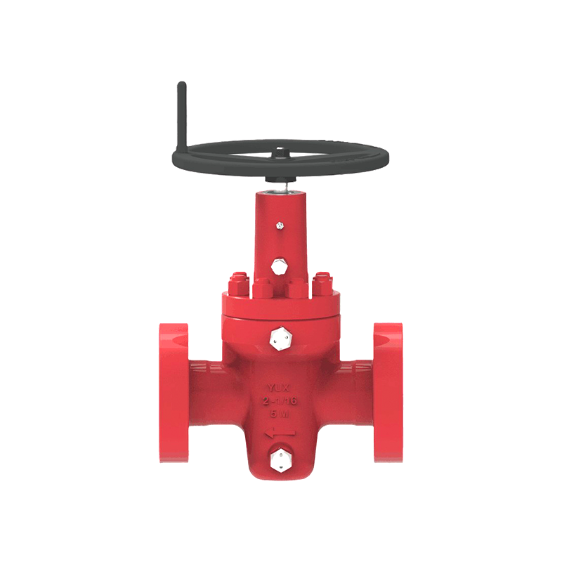
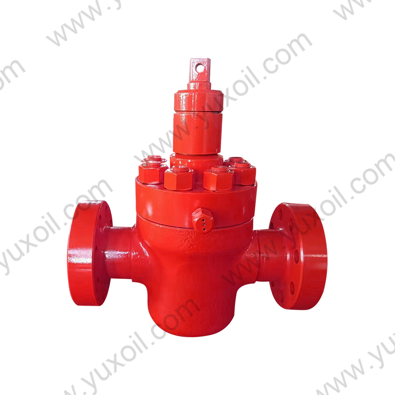
The gate valve is the dominant valve type on high pressure oilfield wellheads and Christmas trees. It operates by raising or lowering a solid gate perpendicular to the flow path, providing a full-bore, bi-directional, bubble-tight shut-off when closed. When fully open, the gate retracts completely out of the flow path, creating zero flow restriction — a critical feature for wellbores where wireline tools, coiled tubing, and perforating guns must pass through the valve.
Gate valves for high pressure oilfield service are governed by API 6A (wellhead and Christmas tree equipment) or API 6D (pipeline service). API 6A gate valves are rated to working pressures of 2,000–20,000 psi and must be specified with a working pressure class, material class (AA through HH for sour service), product specification level (PSL 1–4), and performance requirement (PR1 or PR2). For any wellhead master valve or wing valve, minimum PSL 3 and PR2 are the correct baseline — never PSL 1 or PR1 for production service.
Ball valves use a spherical closure element with a through-bore that aligns with the flow path when open and rotates 90° to block flow when closed. The quarter-turn operation makes ball valves significantly faster to actuate than gate valves, and their simple rotary motion is more compatible with electric and pneumatic actuators used in automated shutdown systems.
At high pressures, trunnion-mounted ball valves are the correct choice. In a floating ball design, line pressure pushes the ball against the downstream seat to create the seal — at 5,000 psi and above, the resulting seat contact force exceeds what most elastomeric seats can handle without deformation. Trunnion-mounted designs fix the ball on top and bottom trunnions, transferring line pressure loads to the body structure rather than the seats, and allowing spring-loaded seats to maintain consistent sealing force independent of pressure. Floating ball valves are appropriate only up to approximately 1,500 psi in oilfield service.
Check valves allow flow in one direction only, closing automatically when flow attempts to reverse. They contain no external operator — closure is driven entirely by the pressure differential across the valve. In high pressure oilfield applications, check valve failure (failure to close or failure to hold closed) can allow high-pressure wellbore fluids to backflow into injection systems, contaminate chemical injection lines, or damage compressors and pumps.
For sour service check valves, the same NACE MR0175 material requirements that govern gate valve bodies apply — all wetted components must meet the hardness and alloy requirements for the H₂S partial pressure present, including the spring, disc, and seat ring.
A choke valve is a throttling device that creates a controlled pressure drop across a restricted orifice, allowing operators to manage wellhead flowing pressure and production rate. Unlike isolation valves — which are either fully open or fully closed — choke valves operate continuously in the partially open position under severe erosive and cavitating flow conditions. A choke valve on a 10,000 psi gas well may experience a pressure drop of 8,000–9,500 psi across a tungsten carbide trim with a gas velocity approaching sonic at the seat.
Choke valve trim material selection is driven by the erosivity of the produced fluid stream. Tungsten carbide (WC-Co, 94% WC) is the standard trim material for sand-laden or high-velocity gas service, providing 5–10× the erosion resistance of hardened 17-4 PH stainless steel. For highly corrosive or sour service, Stellite 6 overlay or Inconel 625 trim is specified in combination with WC seats.
Needle valves use a slender, tapered needle-shaped plunger that seats into a matching conical seat to provide fine, precise flow control in small-diameter, high-pressure instrument and chemical injection lines. They are not designed for full isolation duty — the thin needle-to-seat contact area is not intended to provide bubble-tight shut-off under repeated cycling.
High pressure oilfield needle valves are typically manufactured from 316 stainless steel, Inconel 625, or duplex stainless steel for body and needle materials, with connection sizes of 1/4-inch to 1-inch NPT or Autoclave-style medium-pressure (MP) and high-pressure (HP) cone-and-thread connections rated to 20,000 psi.
Plug valves use a cylindrical or tapered plug with a through-port that rotates 90° within the body to open or close the flow path — functionally similar to a ball valve but with a cylindrical rather than spherical closure element. In high pressure oilfield service, lubricated plug valves are the most common variant: a sealant is injected into the annular space between the plug and body, providing lubrication during rotation and supplementing the primary metal-to-metal seal.
Plug valves in high pressure oilfield service are most commonly rated to 3,000–10,000 psi and manufactured per API 6D or API 6A depending on service location. Above 10,000 psi, ball and gate valves are generally preferred due to the difficulty of maintaining consistent sealant injection performance at very high differential pressures.
The table below summarizes the functional differences between the six high pressure oilfield valve types to support initial selection:
| Valve Type | Primary Function | Max Pressure (typical) | Flow Control Capability | Tool Passage | Governing Standard |
|---|---|---|---|---|---|
| Gate | Full-bore isolation | 20,000 psi | On/off only | Yes (full-bore) | API 6A / API 6D |
| Ball | Fast-acting isolation / ESD | 15,000 psi | On/off only | Yes (full-bore) | API 6D / API 6A |
| Check | Backflow prevention | 15,000 psi | None (automatic) | No | API 6D / API 594 |
| Choke | Pressure drop / rate control | 20,000 psi | Continuous throttling | No | API 6A |
| Needle | Precision metering / instrument isolation | 20,000 psi | Fine throttling (small lines) | No | ASME B16.34 / mfr spec |
| Plug | Multiport diversion / slurry isolation | 10,000 psi | On/off / multiport | No | API 6D / API 599 |
Valve selection should follow a structured sequence. Skipping steps — particularly jumping to manufacturer catalogs before defining service conditions — is the root cause of most misspecification failures.
Start with what the valve must do, not what type it is. There are only four valve functions in oilfield service:
For each valve location, establish the full service envelope before contacting a manufacturer:
The installation location determines which API or ASME standard governs the valve specification:
| Installation Location | Governing Standard | Applicable Valve Types |
|---|---|---|
| Wellhead and Christmas tree | API 6A | Gate, choke, needle |
| Pipeline and transmission | API 6D | Gate, ball, check, plug |
| Subsea wellhead and tree | API 17D | Gate, ball, check |
| Downhole (tubing-conveyed) | API 14A | Ball (SSSV), check |
| Surface process and separation | ASME B16.34 / API 6D | Ball, gate, check, needle |
Once the valve type and governing standard are established, the final specification layer is the quality and testing requirement. For API 6A valves, this means PSL and PR. For API 6D valves, this means specifying the supplemental testing requirements from the standard's annex, including low-pressure seat tests, NDE on body welds, and Charpy impact testing. Always require a full material traceability and test documentation package as a condition of delivery — without it, you cannot demonstrate regulatory compliance or perform root cause analysis if the valve fails in service.
Two service environments — sour gas (H₂S-containing) and high pressure / high temperature (HPHT, defined as above 15,000 psi and/or above 300 °F) — impose requirements beyond those met by standard API valve specifications. In these environments, standard catalog valves meeting the nominal API pressure class and material grade are frequently inadequate, and operators must engage manufacturers in a detailed design review before specifying.
The six types of high pressure oilfield valves — gate, ball, check, choke, needle, and plug — are not interchangeable. Each exists because it solves a specific flow control problem that the others cannot solve as effectively. Selecting the right valve starts with defining the required function, not browsing a product catalog: isolation, throttling, non-return, or diversion. From there, service pressure, fluid composition, temperature, cycle frequency, and regulatory standard narrow the field to a precise specification.
In high pressure oilfield environments where operating pressures reach 10,000–20,000 psi and fluids may contain H₂S, CO₂, sand, and produced water, a valve that is correctly typed but incorrectly specified for material class, PSL, or sour service compliance is as dangerous as the wrong valve type entirely. The four-step framework — function, service conditions, governing standard, quality level — applied consistently at the engineering stage is the most reliable way to ensure every valve in a wellhead system performs as designed for its full service life.
 No. 161, Yanhe Middle Road, Yanhe Town, Jianhu County, Yancheng City, Jiangsu Province, China
 +86-13961903990
 +86-515-86598285
 +86-515-86590688
Copyright © Jianhu Yuxiang Machinery Manufacturing Co., Ltd. All Rights Reserved.
 Login Wholesale High Pressure Wellhead/Drilling Equipment Manufacturer

 English
 русский
 Español