-

+86-13961903990

+86-13961903990
Industry News
 Home / News / Industry News / Wellhead Diagram Explained: A Practical Guide to Components and Symbols
 2026.11.02
 Industry News
Content
If you have ever stared at a wellhead drawing and wondered where the casing spool ends and the tubing head begins, you are not alone. A wellhead diagram is one of those documents that looks simple at first glance but carries a surprising amount of engineering detail. Whether you are a field technician, a procurement engineer, or someone preparing a maintenance plan, understanding what the diagram is telling you can save time, reduce errors, and make conversations with suppliers far more productive.
A wellhead diagram is a simplified cross-sectional or schematic view of the equipment installed at the top of a well. It shows how the main pressure-containing components stack together, where each valve sits, and how fluids move from the casing or tubing up into the surface flowline. It is not usually a fabrication drawing. Instead, it is a communication tool that helps engineers, operators, and equipment suppliers agree on the arrangement before anything is installed.
Diagrams come in a few practical forms. A cross-section shows the internal bodies and seals, which is helpful for understanding how pressure is contained. A schematic focuses on flow paths and valve positions, which is more useful for operating procedures. A process flow diagram may combine the wellhead with downstream equipment such as manifolds and separators. Knowing which type you are looking at keeps you from over-reading details that were never meant to be dimensional.
Most wellhead diagrams follow a bottom-up logic. The deepest component appears at the bottom, and each component above it represents a higher point in the wellhead stack. This mirrors the way the equipment is actually assembled on site: casing spools first, then tubing heads, then the christmas tree and flowline connections. Once you recognise that vertical order, reading the rest of the diagram becomes much easier.
Almost every wellhead diagram includes a handful of familiar building blocks. The casing head or casing spool sits at the base and provides a landing point for the surface casing. Above it, the tubing head supports the production tubing and seals the tubing-casing annulus. The christmas tree then sits at the top, containing the valves and fittings that control production flow.
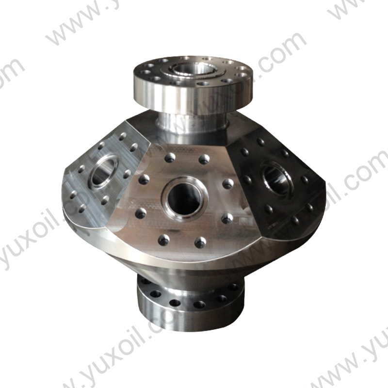
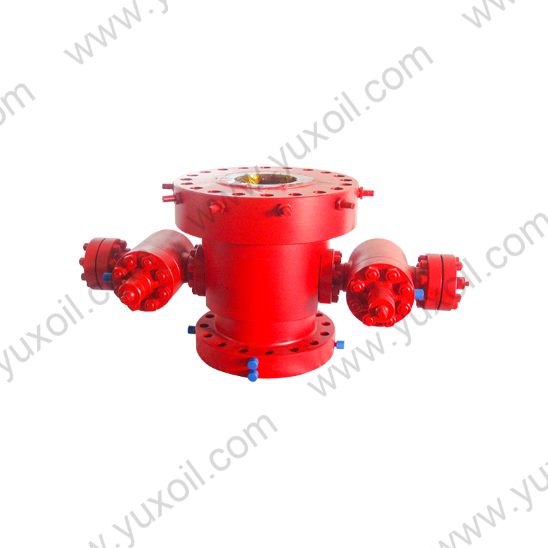 Casing Spool for Wellhead and Fluid Transmission SystemsPositioned at the wellhead base, this casing spool connects four pipelines in a cross-shaped intersection and supports high-pressure, leak-resistant fluid transmission.View Product →
Between these main bodies, you will usually see gate valves, plug valves, pressure gauges, and sometimes a choke. Each one has a specific job. Gate valves provide isolation, plug valves offer quick quarter-turn shutoff, and chokes regulate flow rate and pressure. A wellhead diagram typically labels these items clearly, because a single misplaced valve can change the entire operating procedure.
The christmas tree deserves special attention. Its configuration depends on whether the well produces oil, gas, or a mixture, and whether artificial lift or injection is involved. If you want to go deeper into how tree arrangements vary, a good overview of christmas tree models can help you connect the diagram symbols to real equipment choices.
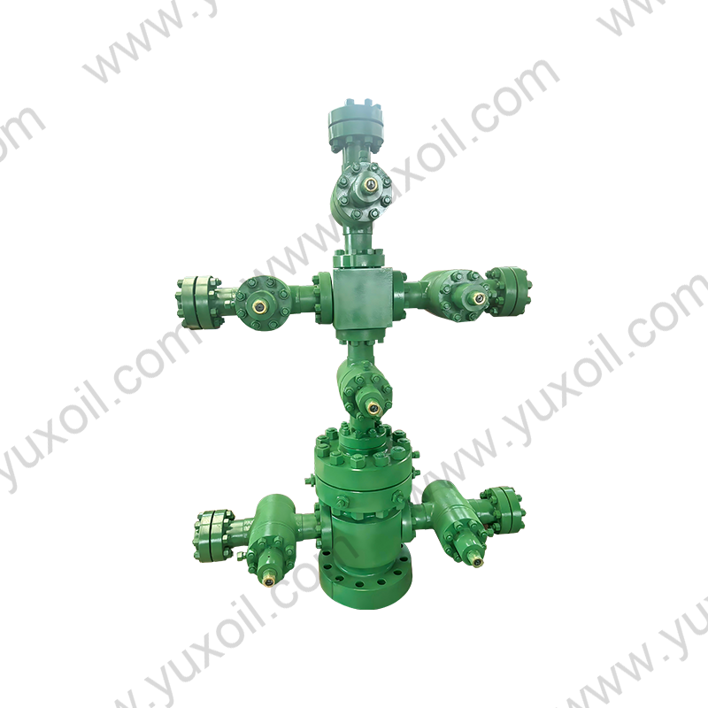
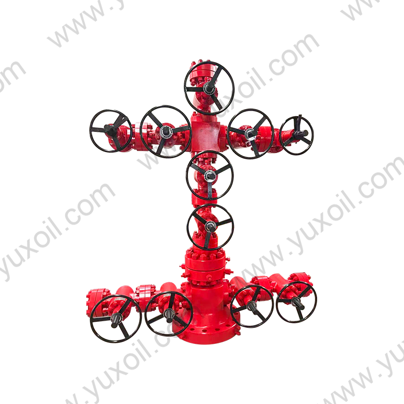 Christmas Tree Equipment for Wellhead Pressure and Flow ControlCentral wellhead system for suspending tubing, controlling pressure and flow, diverting oil or gas, and enabling emergency shutdown with optional safety valves.View Product →
You may also notice small items that are easy to skip: test ports, needle valves, injection points, and drain connections. These details matter during commissioning and maintenance, because they determine how the wellhead can be safely bled off, tested, or chemically treated without disrupting production.
When a drawing lands on your desk, a consistent reading routine keeps you from missing important details. Here is the approach our engineers use most often.
After a few runs through this routine, you will start to recognise the standard layout patterns that appear across most wellhead diagrams. You will also become faster at spotting when something does not look right, which is often the moment when a diagram review saves a costly installation mistake.
Wellhead diagrams use a compact set of symbols and abbreviations. The exact symbol set can vary between operators, but the meanings below are widely understood across the oil and gas industry.
| Symbol or Term | Meaning | Where It Appears |
|---|---|---|
| CS | Casing spool or casing head | Bottom of the stack |
| TH | Tubing head | Above the casing spool |
| XT | Christmas tree | Top of the wellhead |
| GV | Gate valve | On flowlines and tree wings |
| PV | Plug valve | Isolation or switching points |
| CH | Choke | Production flow control |
Remember that a symbol is only as good as its legend. If a diagram does not include a legend, ask for one before you rely on your interpretation. A short phone call or email at the review stage is almost always cheaper than correcting a wrong assumption in the field.
Not every wellhead diagram looks the same, because not every well is completed the same way. A conventional wellhead with separate casing and tubing spools produces a taller, more layered diagram. A compact or monobore wellhead may show fewer stacked bodies, with more functions integrated into a single component.
Frac wellheads introduce another variation. During hydraulic fracturing, the wellhead must handle high pump rates and abrasive fluids. The diagram may show a frac head installed above the tubing head, along with isolation valves and a dedicated flowback path. Recognising these variations helps you avoid ordering components that look similar but serve different purposes.
Pressure class and material grade also shape the diagram. A 5,000 psi wellhead and a 15,000 psi wellhead may share the same basic layout, but the wall thickness, flange dimensions, and sealing details will differ. If the diagram does not clearly state these values, treat them as open questions rather than assumptions.
Casing heads and frac heads are often drawn close together, but they perform different jobs. The casing head supports and seals the casing string, while the frac head provides a connection point for fracturing pumps and high-pressure manifolds. In a frac wellhead diagram, you will typically see the frac head mounted above the tubing head, with isolation valves separating it from the production path.
If your work involves stimulation or well completion, it is worth understanding how these two components interact before you finalise the equipment list. A clear diagram makes it obvious which valves are used during fracturing and which ones remain closed until the well is returned to production. That distinction matters for safety, for valve selection, and for planning maintenance intervals.
A wellhead diagram is only useful if the hardware behind it can actually be supplied. When you are reviewing a drawing, it helps to work with a manufacturer who understands both the standard requirements and the practical details of machining and assembly. Our team at YUXOIL has been producing API 6A valves and oilfield equipment since the company expanded into drilling and production equipment in 2019, building on a foundry and machining background that goes back much further.
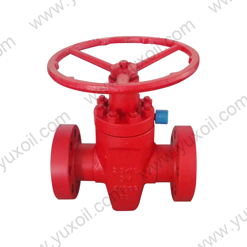
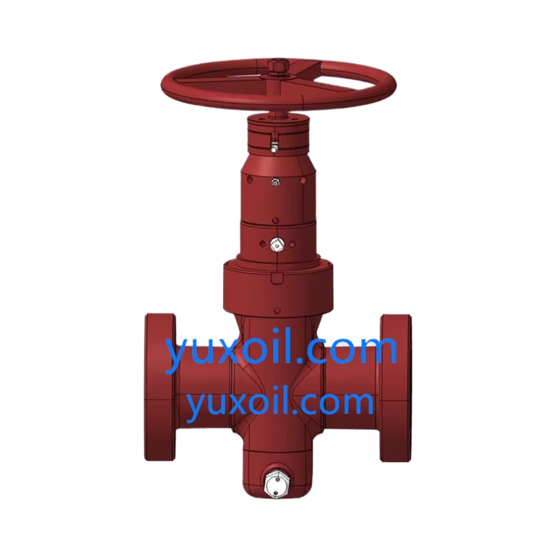
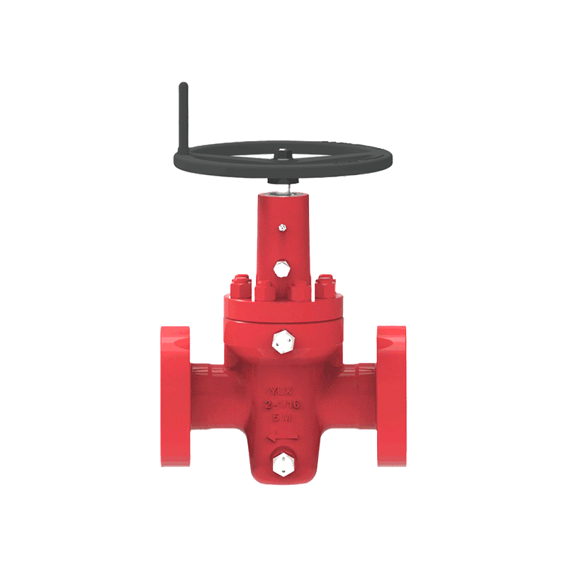 WKM Expanding Gate Valve for API 6A Oilfield IsolationAPI 6A gate valve in flanged or threaded configurations, designed for high-pressure oilfield flow control and isolation with low operating torque.View Product →
If you want to know more about how we approach production and quality control, you can explore our manufacturing capabilities. From casting and machining to assembly and testing, the goal is to make sure the components shown on your diagram arrive ready for installation, with the sizes, pressure ratings, and connection details you specified.
It also helps to keep the diagram updated. A wellhead is rarely static over its lifetime. New valves, injection points, or monitoring equipment may be added as the well matures. An accurate, current diagram is one of the simplest ways to keep field work safe and predictable.
A wellhead diagram is more than a drawing. It is a shared reference point that keeps field crews, engineers, and suppliers on the same page. By reading it from the bottom up, checking the isolation points, and confirming that every symbol matches the legend, you can plan work with greater confidence. And when a diagram raises questions about a specific spool, valve, or tree arrangement, the right manufacturing partner can help you turn that drawing into equipment that performs reliably in the field.
 No. 161, Yanhe Middle Road, Yanhe Town, Jianhu County, Yancheng City, Jiangsu Province, China
 +86-13961903990
 +86-515-86598285
 +86-515-86590688
Copyright © Jianhu Yuxiang Machinery Manufacturing Co., Ltd. All Rights Reserved.
 Login Wholesale High Pressure Wellhead/Drilling Equipment Manufacturer

 English
 русский
 Español