-

+86-13961903990

+86-13961903990
Industry News
 Home / News / Industry News / Actuator Types for Control Valves: How to Choose the Right One for Oil & Gas Service
  2026.09.14
 Industry News
Content
At a fracturing site, the last thing the crew wants is a valve that will not move when the treating pressure is 15,000 psi. The actuator is the interface between the operator and the valve's sealing element, and it determines whether the valve opens in three seconds or requires a full minute of handwheel turning. Choosing an actuator type for a control valve in oil and gas service comes down to four factors: torque demand, response speed, fail-safe behavior, and the power source available at the wellhead.
A control valve actuator converts energy from a power source into the mechanical motion needed to move the valve's closure element. In wellhead and fracturing service, that element is usually a gate or a plug inside an API 6A-rated body. The valve itself defines the actuator requirements: whether the stem moves linearly or rotates, how much torque is required to break the seat seal, and how the valve behaves at the maximum rated differential pressure.
Take a typical API 6A gate valve. The rising stem has to push the gate into the seat to achieve shutoff. Because the differential pressure across the gate can be very high, the breakaway torque is often far greater than the running torque. An actuator sized only for running torque can stall during the opening stroke or fail to seat fully when the line is pressurized. That is why the first step in actuator selection is to know the valve's torque profile, not to compare actuator models side by side. The seat geometry of API 6A standard gate valves plays a big part in setting that profile.
The seat interface also affects torque. On hard-sealed gate valves, the metal-to-metal contact generates enough force to hold pressure, and that force creates friction the actuator must overcome. The same attention to machining tolerances applies to the stem and stuffing box. The manufacturing process determines how precisely the stem is turned and polished, and a rough stem surface increases the torque the actuator must supply. An actuator that looks correctly sized on paper can be undersized on a valve that has not been machined to the same standard.
Five actuator types dominate oil and gas valve service: manual, pneumatic, hydraulic, electric, and electro-hydraulic. Each has a clear niche.
A manual actuator uses a handwheel or hand lever to rotate the stem. It is the simplest and least expensive option, and it still appears on many wellhead valves. Manual actuation makes sense when the valve is operated infrequently, when no power source is available, and when the operating torque is low enough for a person to handle. The limitation is torque. On a large-bore gate valve, the handwheel may need several hundred newton-meters of input effort, which becomes difficult for a single operator. A gearbox multiplies the input force, but it also increases the number of turns required to stroke the valve.
A pneumatic actuator uses compressed air to move a diaphragm or piston, producing a linear or rotary output. Pneumatic units are common in process plants because plant air is usually available, the response is quick, and a spring-return design can fail open or fail closed. In the oil field, however, compressed air is often scarce, and the output force is limited by the supply pressure. Typical plant air is 6 to 8 bar, so a pneumatic cylinder has to be quite large to move a high-pressure gate valve.
Hydraulic actuators generate much higher force density than pneumatic units. By driving a piston with hydraulic fluid at 100 bar or more, a compact cylinder can deliver the torque needed for large gate valves, frac valves, and choke valves. That is why hydraulic actuation is standard on subsea wellheads and frac equipment, where space is limited and the valve must move against a full pressure differential. The trade-off is system complexity: you need a hydraulic power unit, directional control valves, and clean fluid with good filtration.
An electric actuator consists of a motor, a gearbox, and a control interface. It only needs an electrical supply, and it can provide position feedback, torque limiting, and local or remote control. Electric actuators are a strong fit for automated, unattended service. Their weakness is speed and torque at the extremes. A conventional motor cannot match a hydraulic cylinder's instantaneous torque, and an emergency shutdown that must close a valve within seconds may exceed the actuator's capability.
An electro-hydraulic actuator combines an electric motor with a small hydraulic pump and cylinder. It delivers the torque density of hydraulic power while requiring only an electrical source. This makes it a good solution for remote wellhead locations where a central hydraulic power unit is impractical. The added complexity is the downside: more components, more potential failure points, and a higher purchase cost.
The table below narrows down the field. Confirm the details with the valve manufacturer before finalizing a specification.
| Type | Power Source | Torque Density | Typical Speed | Best For |
|---|---|---|---|---|
| Manual | Human effort | Low | Slow | Low-frequency remote valves |
| Pneumatic | Compressed air | Moderate | Fast | Plants with reliable air |
| Hydraulic | Hydraulic fluid | High | Very fast | High-pressure wellhead and frac service |
| Electric | Electric motor | Moderate | Moderate | Automated production service |
| Electro-hydraulic | Motor + hydraulic pump | High | Fast | Remote wellheads without hydraulic power unit |
Notice that no single row represents a definitive answer. The right choice depends on the specific valve torque, the required stroking speed, the failure position you need, and the available power source.
Safety and stem protection drive actuator selection for wellhead and fracturing valves. On a Christmas tree, the master valve and wing valves are often manual because they are not cycled frequently. But on a frac job, the frac head and high-pressure manifolds connect the wellhead to pumps that deliver 10,000 to 20,000 psi. The operator needs to position the block valves quickly and positively. Hydraulic or electro-hydraulic actuation is the standard solution, because the crew can cycle a valve under full pressure without standing directly behind it.
For API 6A gate valves that must provide positive shutoff, the actuator has to be matched to the gate's stroke. The FC gate valve is one API 6A design used in wellhead and manifold service, and it can be paired with manual, hydraulic, or electric actuation. When paired with an actuator, the stem alignment must be checked carefully. A misaligned actuator can impose side loading on the stem, which distorts the seal surfaces and produces leakage.
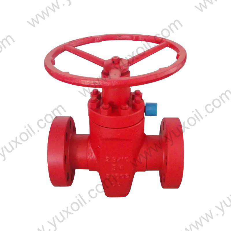
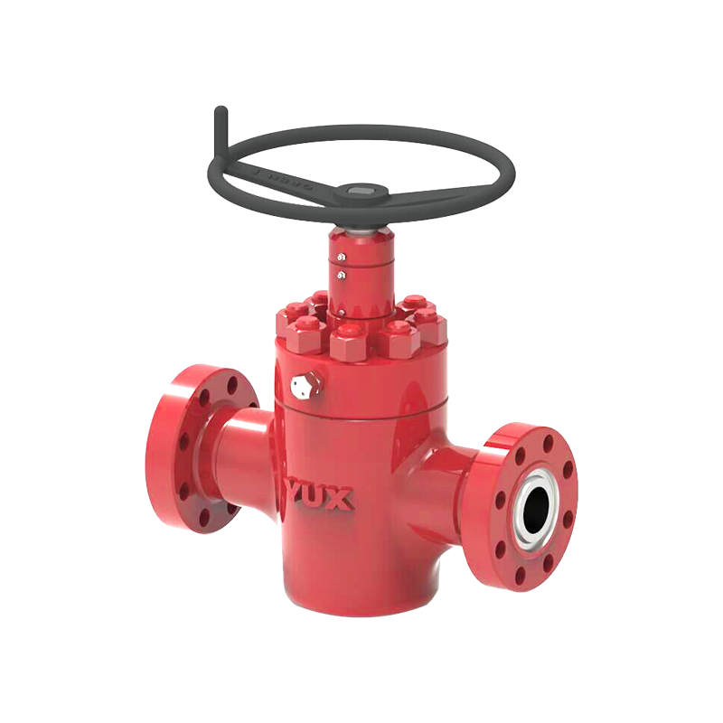 FC Gate Valve for API 6A Wellhead and Manifold ServiceThe FC gate valve meets API 6A standards with forged alloy steel body and hard-faced sealing surfaces. Its reliable performance makes it suitable for drilling fluid control in kill, choke, and mud manifolds.View Product →
An expanding gate valve uses a mechanism that moves the gate before it expands into the seat, creating a metal-to-metal seal. The expansion step adds to the breakaway torque, so the actuator must be sized for the fully expanded position. If the valve is automated, a limit switch box should show the actual position of the gate, not just the rotation of the actuator output shaft.
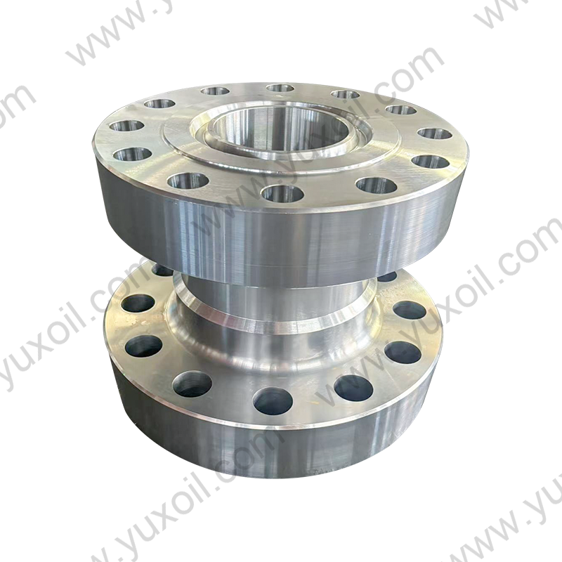
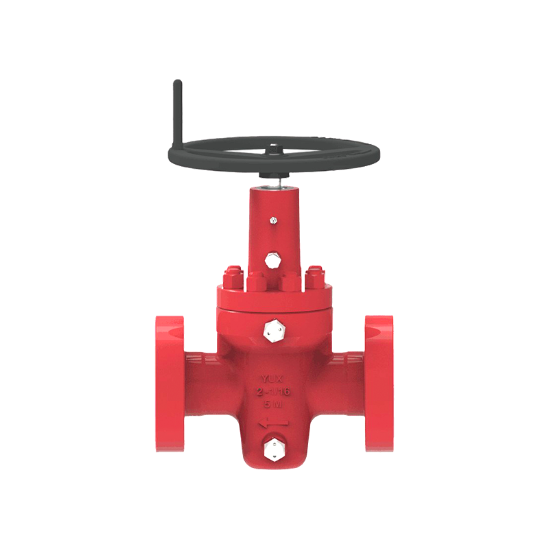 WKM Expanding Gate Valve with Metal-to-Metal SealThis expanding gate valve offers low operating torque and metal seal design, available in flanged or threaded ends. It suits high-pressure environments and ensures leak-free operation.View Product →
Where compressed air is not available at a remote wellhead, automated actuation needs either electric power or a hydraulic pump. At a frac site, the pump skid already includes hydraulic power, so hydraulic actuation is simpler to integrate than pneumatic. Electric actuators remain a good match for production lines where the operator wants local or supervisory control.
This six-step process applies whether you are specifying a valve for a new wellhead or replacing an actuator on an existing valve.
For lower-torque production service, the choice of gate valve design can influence the actuator package. API 6A gate valves are available in several structural configurations, and the selected design affects the torque the actuator has to overcome. The FLS gate valve is an API 6A design used in wellhead and manifold service.
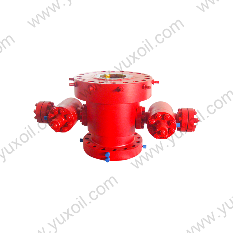
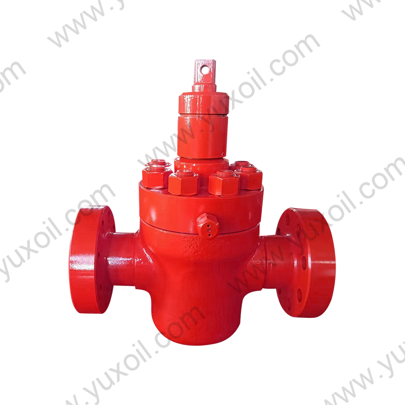 FLS Gate Valve with Rear Seat Sealing and Forged BodyThe FLS gate valve features a metal-to-metal body seal and rear seat structure, facilitating packing replacement under pressure. Its forged alloy steel body resists corrosion and wear for long-lasting service.View Product →
The right actuator type for a control valve is a compromise between available power, torque demand, response speed, and fail-safe behavior. Manual actuation is practical for infrequent low-torque service; pneumatic and electric actuators fit automated production pipelines; and hydraulic or electro-hydraulic systems are the right choice for high-pressure, large-bore wellhead and fracturing valves. Start with the valve's torque profile, define the failure mode, then match the actuator to the service.
That approach avoids the two most common mistakes: over-sizing the actuator for a valve that never needs that much torque, and under-sizing it for a valve that does.
 No. 161, Yanhe Middle Road, Yanhe Town, Jianhu County, Yancheng City, Jiangsu Province, China
 +86-13961903990
 +86-515-86598285
 +86-515-86590688
Copyright © Jianhu Yuxiang Machinery Manufacturing Co., Ltd. All Rights Reserved.
 Login Wholesale High Pressure Wellhead/Drilling Equipment Manufacturer

 English
 русский
 Español